
1. บทนำ
The Wonrabai ESP32-S3-LCD-1.28 is a low-cost, high-performance microcontroller development board designed by Waveshare. It integrates a 1.3-inch round IPS LCD with 240x240 resolution, a portable recharge manager, and a 6-axis sensor (3-axis accelerometer and 3-axis gyroscope). This design facilitates rapid development and product integration.
The board utilizes the ESP32-S3R2 System-on-Chip (SoC), which features low-power Wi-Fi and Bluetooth 5.0 capabilities. It includes an external 16MB Flash and 2MB PSRAM. The SoC also incorporates hardware encryption accelerators, a Random Number Generator (RNG), HMAC, and a digital signature module, addressing IoT security requirements. Its various low-power operating modes are suitable for IoT, mobile devices, wearables, smart homes, and other application scenarios.
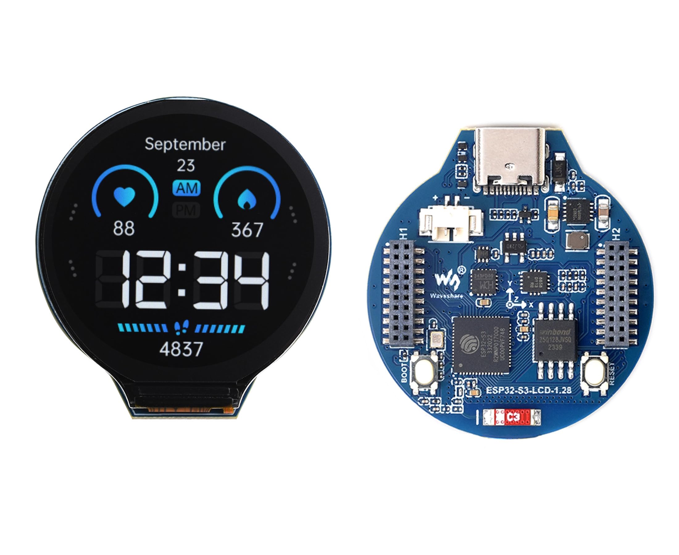
Figure 1: Wonrabai ESP32-S3-LCD-1.28 Development Board with round LCD display.
2. คุณสมบัติหลัก
- Equipped with Xtensa LX7 dual-core 32-bit processor, operating at up to 240 MHz.
- Supports 2.4 GHz Wi-Fi (802.11 b/g/n) and Bluetooth 5 (BLE), with an integrated antenna.
- Built-in 512 KB SRAM and 384 KB ROM, with 2 MB integrated PSRAM and an external 16 MB Flash memory.
- Integrated 1.3-inch round IPS LCD display with 240x240 resolution and 65K colors.
- Integrated QMI8658 6-axis IMU (3-axis accelerometer and 3-axis gyroscope) for motion gesture detection.
- Integrated 3.7V lithium battery recharge/discharge header and GPIO headers.
- 30 multi-functional GPIO pins with configurable pin functions for flexible development and integration.
- USB Type-C connector for modern connectivity and ease of use.
- Supports flexible clocking and independent power supply configuration for low power consumption in various scenarios.
- Integrated with a full-speed USB serial port controller, allowing flexible GPIO pin function configuration.

รูปที่ 2: เกินview of the ESP32-S3-LCD-1.28 board highlighting its key features.
3. มีอะไรอยู่บนเรือบ้าง
The following diagram illustrates the main components and their locations on the ESP32-S3-LCD-1.28 development board.

รูปที่ 3: รายละเอียด view of the board's components.
- ESP32-S3R2: The System-on-Chip (SoC) with Wi-Fi and Bluetooth, operating up to 240MHz, with onboard 2MB PSRAM.
- W25Q128JVSIQ: 16MB NOR-Flash memory.
- QMI8658: 6-axis IMU, including a 3-axis gyroscope and a 3-axis accelerometer.
- ME6217C33M5G: 800mA output, low dropout, high rejection rate.
- CH343P: USB to UART chip for serial communication.
- ETA6096: High-efficiency Lithium battery recharge manager.
- 1.27mm pitch headers: Adapting multiple GPIO pins for external connections.
- ปุ่มบูต: Press before resetting to enter download mode.
- ปุ่มรีเซ็ต: รีเซ็ตบอร์ด
- หัวต่อแบตเตอรี่ MX1.25: MX1.25 2P connector, for 3.7V Lithium battery, supports charging and discharging.
- ขั้วต่อ USB Type-C: USB to UART, for programming and log printing.
- 2.4GHz ceramic antenna: เสาอากาศแบบรวมสำหรับระบบสื่อสารไร้สาย
4. ข้อมูลจำเพาะ
Detailed technical specifications for the ESP32-S3-LCD-1.28 development board.
4.1. ข้อกำหนดทั่วไป
- ยี่ห้อ: Wonrabai
- ชื่อรุ่น : อีเอสพี32เอส3
- ความจุหน่วยความจำ: 16 MB (แฟลช)
- เทคโนโลยีการเชื่อมต่อ: ยูเอสบี, ไวไฟ
- จำนวนโปรเซสเซอร์: 2 (Dual-core LX7)
- พอร์ต USB ทั้งหมด: 1 (ประเภท C)
- ส่วนประกอบที่รวมอยู่: ESP32-S3-LCD-1.28 x1
4.2. LCD Parameters
| พารามิเตอร์ | ค่า | พารามิเตอร์ | ค่า |
|---|---|---|---|
| ชิปแสดงผล | GC9A01A | หน้าจอแสดงผล | เอสพีไอ |
| ปณิธาน | 240(สูง)RGB x 240(V) | ขนาดจอแสดงผล | Φ32.4มม. |
| แผงแสดงผล | ไอพีเอส | พิกเซล | 0.135 (H) x 0.135 (V) มม |
4.3. IMU Parameters (QMI8658)
| ชื่อเซนเซอร์ | ค่า |
|---|---|
| ปณิธาน | 16 บิต |
| Accelerometer Measurement Range (Optional) | ±2, ±4, ±8, ±16g |
| Gyroscope Resolution | 16 บิต |
| Gyroscope Measurement Range (Optional) | ±16, ±32, ±64, ±128, ±256, ±512, ±1024, ±2048°/sec |

Figure 4: Technical parameters for the integrated LCD and IMU.
5. Pinout and Hardware Description
The ESP32-S3-LCD-1.28 board provides numerous GPIO pins for flexible connectivity and expansion. Understanding the pinout is crucial for custom applications.

Figure 5: GPIO pin assignments and functions.
5.1. อินเทอร์เฟซฮาร์ดแวร์
- อินเทอร์เฟซ Type-C: The development board uses the CH343P chip for USB to UART communication. Connect the UART_TXD (GPIO43) and UART_RXD (GPIO44) of ESP32-S3 for programming and log printing. Automatic download circuit allows firmware to be downloaded directly after connecting the Type-C cable.
- 1.27mm Pitch Headers: These headers expose most of the GPIOs for external connection. GPIOs can be configured for I2C, SPI, and other peripheral functions. VSYS can directly input 5V to power the development board.
- อินเทอร์เฟซ LCD: The onboard 1.28-inch screen uses 4-wire SPI communication. SPI rate can be increased to 80MHz. I2C communication (development board using GPIO2) controls the backlight brightness. GPIO4 and GPIO5 can be soldered on their own with small-current devices such as vibration motors.
- อินเทอร์เฟซ I2C: ESP32-S3 provides multiple hardware I2C interfaces. GPIO6 (SDA) and GPIO7 (SCL) pins are used for I2C bus. The onboard QMI8658 six-axis inertial measurement unit and LCD touch control chip are integrated via I2C.
- MX1.25 Connector: GPIO1 of the development board is used to measure the battery voltagอี ปริมาณแบตเตอรี่tage is connected to GPIO1 using a 200K and 100K series voltage divider. The ESP32-S3 series has two 12-bit SAR ADC measurement units. The source code converts the voltage to the formula 3.3 / (1+2) * AD_Value.

Figure 6: Detailed hardware interface descriptions and pin mapping table.
5.2. Pinout Table
| เข็มหมุด | ESP32-S3R2 | จอแอลซีดี | เอ็มเอ็กซ์1.25 | คิวเอ็มไอ8658 | อื่น |
|---|---|---|---|---|---|
| GPIO0 | GPIO0 | บูต 0 | |||
| GPIO1 | GPIO1 | เอดีซี | |||
| GPIO5 | GPIO5 | TP_INT | |||
| GPIO6 | GPIO6 | เอสดีเอ | |||
| GPIO7 | GPIO7 | เอส ซี แอล | |||
| GPIO8 | GPIO8 | LCD_DC | |||
| GPIO9 | GPIO9 | LCD_CS | |||
| GPIO10 | GPIO10 | จอ LCD_ซีแอลเค | |||
| GPIO11 | GPIO11 | จอแอลซีดี_MOSI | |||
| GPIO12 | GPIO12 | จอแอลซีดี_RST | |||
| GPIO40 | GPIO40 | จอแอลซีดี_BL | |||
| GPIO47 | GPIO47 | อินที1 | |||
| GPIO48 | GPIO48 | อินที2 |
6. คู่มือการติดตั้ง
6.1. การเชื่อมต่อเริ่มต้น
To begin using your ESP32-S3-LCD-1.28 development board, connect it to your computer using a USB Type-C cable. The board will power on and establish a serial communication link via the integrated CH343P USB to UART chip. This connection is used for both power and data transfer, including programming and debugging.
6.2 การตั้งค่าสภาพแวดล้อมซอฟต์แวร์
For programming the ESP32-S3, you will typically use the Espressif IoT Development Framework (ESP-IDF) or Arduino IDE with ESP32 board support.
- ไดรเวอร์: Ensure your operating system has the necessary drivers for the CH343P USB-to-UART chip. These are usually installed automatically, but may require manual installation on some systems.
- สภาพแวดล้อมการพัฒนา: Install your preferred ESP32 development environment. Refer to the official Espressif documentation or community guides for detailed setup instructions.
- แหล่งข้อมูลออนไลน์: For comprehensive tutorials and documentation, refer to the online resources provided by the manufacturer. A common resource link is n9.cl/grkoe.
6.3. Battery Connection (Optional)
The board supports a 3.7V single-cell lithium battery via the MX1.25 2P connector. This allows for portable operation and battery management.
- Connect a 3.7V single-cell lithium battery (e.g., 500mAh or below) to the MX1.25 battery header (component 10 in Figure 3).
- The integrated ETA6096 chip manages battery charging and discharging.
- บันทึก: The board is equipped with an efficient charging and discharging management chip, ETA6096, and an MX1.25 battery interface. The charging current is set to 1A. Users can change the charging current by replacing the R15 resistor. It is recommended to use a 3.7V single-cell lithium battery with a capacity of 500mAh or below.
7. คู่มือการใช้งาน
7.1. Powering On and Display
Once connected via USB or battery, the board will power on. The integrated 1.3-inch round IPS LCD will activate. You can program the ESP32-S3 to display various information, graphics, or user interfaces on this screen.
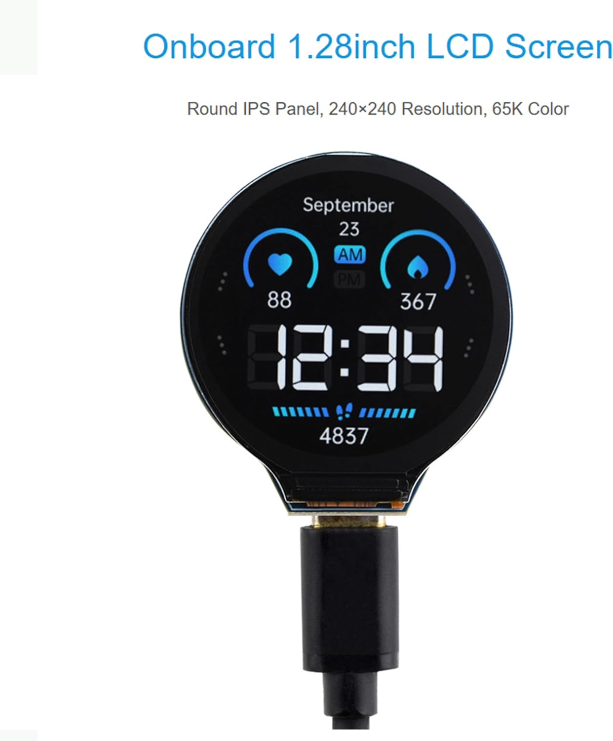
รูปที่ 7: อดีตample of the onboard LCD display in use.
7.2. การเขียนโปรแกรมและการพัฒนา
The ESP32-S3-LCD-1.28 is designed for flexible programming.
- การอัปโหลดเฟิร์มแวร์: Connect the board to your computer via the Type-C USB port. Use your chosen development environment (e.g., ESP-IDF, Arduino IDE) to compile and upload your code. The automatic download circuit simplifies this process.
- การใช้งาน GPIO: Utilize the 30 multi-functional GPIO pins (exposed via 1.27mm pitch headers) to connect external sensors, actuators, or other modules. Refer to the pinout diagram (Figure 5) and pinout table for specific assignments.
- การบูรณาการ IMU: The integrated QMI8658 6-axis IMU can be accessed via I2C (GPIO6/SDA, GPIO7/SCL) to detect motion gestures, acceleration, and angular velocity.
- Wi-Fi และบลูทูธ: Leverage the integrated 2.4 GHz Wi-Fi and Bluetooth 5 (BLE) capabilities for wireless communication in your projects.
7.3. Low Power Operation
The ESP32-S3 supports various low-power modes. You can configure flexible clocking and independent power supply settings for different modules to optimize power consumption, making it suitable for battery-powered applications.
8. การบำรุงรักษาและการดูแล
- การดูแลเสาอากาศ: When using the development board, pay attention to the ceramic antenna area. Avoid covering the ceramic antenna with PCB boards, metal, or plastic components, as this can degrade wireless performance.
- การจัดการแบตเตอรี่: To prevent overcharging and over-discharging of the battery, stop discharging when the fully charged 4.2V lithium battery discharges to 3.7V. Always use appropriate battery protection circuits if not relying solely on the onboard manager.
- การทำความสะอาด: Keep the board clean and free from dust and debris. Use a soft, dry brush or compressed air for cleaning. Avoid using liquids.
- พื้นที่จัดเก็บ: เก็บบอร์ดไว้ในที่แห้งและป้องกันไฟฟ้าสถิตเมื่อไม่ได้ใช้งาน
9 การแก้ไขปัญหา
- เมนบอร์ดไม่เปิดใช้งาน:
- Ensure the USB Type-C cable is securely connected to both the board and your computer/power source.
- หากใช้แบตเตอรี่ โปรดตรวจสอบให้แน่ใจว่าได้ชาร์จแบตเตอรี่แล้วและเชื่อมต่อกับหัวต่อ MX1.25 อย่างถูกต้อง
- ลองใช้สายเคเบิลหรือพอร์ต USB อื่น
- ความล้มเหลวในการอัพโหลดเฟิร์มแวร์:
- Check if the correct COM port is selected in your development environment.
- Ensure the necessary USB-to-UART drivers (CH343P) are installed.
- Press and hold the BOOT button (component 8) while pressing and releasing the RESET button (component 9) to enter download mode, then release BOOT.
- ตรวจสอบว่าโค้ดของคุณคอมไพล์ได้โดยไม่มีข้อผิดพลาด
- จอแสดงผลไม่ทำงาน:
- Confirm that your code initializes the LCD correctly and sends data to it.
- Check for any physical damage to the display or its connections.
- Ensure the backlight (LCD_BL) is enabled in your software.
- ปัญหาการเชื่อมต่อ Wi-Fi/Bluetooth:
- Ensure the ceramic antenna area is not obstructed.
- Verify your code correctly configures and initializes the Wi-Fi or Bluetooth module.
- Check for correct network credentials or pairing procedures.
10. การรับประกันและการสนับสนุน
For warranty information, technical support, and further assistance, please refer to the official Wonrabai website or contact their customer service directly. Online documentation and community forums often provide valuable resources for development boards like the ESP32-S3-LCD-1.28.