
Walfront WALFRONTwqn2b5fksg
Walfront Smart Energy Monitor User Manual
Model: WALFRONTwqn2b5fksg
1. บทนำ
This manual provides detailed instructions for the installation, operation, and maintenance of the Walfront Smart Energy Monitor. This device is designed for real-time monitoring of electricity usage in single-phase systems, featuring a 200A CT current transformer for accurate measurements. It integrates with smart home systems for efficient electricity consumption management and is suitable for monitoring both urban power grids and PV solar system generation.

Figure 1: The Walfront Smart Energy Monitor unit with its accompanying 200A Current Transformer (CT) clamp. The main unit is white with terminal blocks, and the black CT clamp is connected via a red and black wire.
2. ข้อมูลด้านความปลอดภัย
- อันตรายจากไฟฟ้า: Installation and servicing must be performed by qualified personnel only. Ensure power is disconnected before installation or maintenance.
- เล่มที่tagอี ช่วง: ห้ามใช้เกินปริมาตรการทำงานที่กำหนดไว้tagมีช่วงแรงดันไฟฟ้าตั้งแต่ AC90-250V.
- หม้อแปลงกระแส: ตรวจสอบให้แน่ใจว่า CT clamp is correctly installed around the live wire as per the wiring diagram. Incorrect installation may lead to inaccurate readings or damage.
- สิ่งแวดล้อม: Do not expose the device to extreme temperatures, humidity, or corrosive environments beyond the specified operating conditions (-20-55℃, ≤90% non-condensing humidity).
- ถอดชิ้นส่วน: Do not attempt to disassemble or modify the device. This will void the warranty and may pose a safety risk.
3. ส่วนประกอบและคุณสมบัติของผลิตภัณฑ์
The Smart Energy Monitor consists of the main monitoring unit and a Current Transformer (CT) clampคุณสมบัติหลักได้แก่:
- การตรวจสอบปริมาณแบบเรียลไทม์tage, current, power factor, active power, and frequency.
- Built-in relay for power-saving settings and control.
- App data storage for historical energy consumption records.
- 10A dry output for controlling external devices.
- Integrated 2.4GHz antenna for Wi-Fi connectivity.
- Support for schedule-based control and Over-The-Air (OTA) updates.

รูปที่ 2: รายละเอียด view of the Smart Energy Monitor's components. It shows the LED indicator, Reset & On/Off Button, CT (Current Transformer) input terminals, and Output terminals. Instructions for connecting the split core CT (black wire to '-' and white wire to '+') are also visible.

Figure 3: A close-up image of the terminal block on the Smart Energy Monitor. Labels for 'N' (Neutral), 'L' (Live), 'CT' (Current Transformer input), and output terminals are clearly visible, along with regulatory markings.
4. ข้อมูลจำเพาะ
| พารามิเตอร์ | ค่า |
|---|---|
| Clamp การจัดอันดับ | 120A (Note: Product title mentions 200A, refer to specific CT provided) |
| บริการ Wi-Fi มาตรฐาน | 802.11 B/G/N20/N40 at 2.4GHz |
| บีอี | 5.2 พลังงานต่ำ |
| ความถี่ในการทำงาน | 2.4GHz (built-in antenna) |
| ฉบับทำงานtage | AC90-250V 50 / 60Hz |
| ช่วงการวัดกระแสไฟฟ้า | 0.2A-120A |
| Maximum Load Current (Dry Output) | 10เอ |
| ความแม่นยำในการวัดการสอบเทียบ | ≤100W (within ±2W), >100W (within ±2%) |
| Report Cycle | ทุก ๆ 15 วินาที |
| ช่วงอุณหภูมิ | -20-55℃ |
| ช่วงความชื้น | ≤90% ไม่ควบแน่น |
| วิธีการติดตั้ง | 35MM DIN Rail |
| ขนาดแพ็คเกจ | 5.31 x 4.25 x 2.36 นิ้ว |
| น้ำหนักสินค้า | 5.47 ออนซ์ |
5. คู่มือการติดตั้ง
Follow these steps for proper installation. Ensure all power is disconnected before proceeding.
- การติดตั้ง: Install the Smart Energy Monitor onto a standard 35MM DIN rail within your electrical panel.
- การเดินสายไฟหลัก: Connect the Live (L) and Neutral (N) wires from your circuit breaker to the corresponding 'L' and 'N' input terminals on the monitor.
- Connecting the CT Clamp: Pass the live wire of the circuit you wish to monitor through the opening of the CT clamp. Connect the CT clamp's wires to the 'CT' input terminals on the monitor. Ensure the polarity is correct: connect the black wire of the CT to the '-' terminal and the white wire to the '+' terminal.
- Connecting Load (Optional): If using the 10A dry output to control a load, connect the load's control wires to the output terminals.
- เปิดเครื่อง: เมื่อเชื่อมต่อทั้งหมดอย่างปลอดภัยและได้รับการตรวจสอบแล้ว ให้จ่ายไฟให้กับวงจรอีกครั้ง

Figure 4: A clear wiring diagram illustrating the connection of the Smart Energy Monitor. It shows the circuit breaker, the monitor unit with L, N, and CT inputs, and the CT clamp positioned around the live wire leading to the load. The diagram also indicates the output terminals for controlling a load.
6. คู่มือการใช้งาน
After successful installation, the device will power on. Follow these steps to configure and operate your Smart Energy Monitor:
- ดาวน์โหลดแอป: Download the dedicated mobile application (refer to the QR code on the packaging or the included user manual for app details).
- การจับคู่อุปกรณ์: Open the app and follow the on-screen instructions to add a new device. The monitor's LED indicator will guide you through the pairing process (refer to Section 7 for LED status).
- การเชื่อมต่อ Wi-Fi: Connect the monitor to your 2.4GHz Wi-Fi network via the app.
- การตรวจสอบตามเวลาจริง: Once connected, the app will display real-time data including voltage, current, power factor, active power, and frequency.
- Data Storage and Analysis: The app stores energy consumption records, allowing you to view historical data for different time intervals (daily, weekly, monthly).
- ฟังก์ชั่นการควบคุม: Use the app to control the 10A dry output, set schedules for power-saving, and manage other smart functions.

Figure 5: An illustration showing the Smart Energy Monitor installed in an electrical panel, connected to a circuit. Alongside, a smartphone displays the monitor's application interface, showing a graph of 'Total Energy Consumed', demonstrating the real-time data monitoring capability. The image also highlights the 10A dry contact output for controlling devices like heaters, lamps, contactors, and heat pumps.
7. ไฟแสดงสถานะ LED
The LED indicator on the PC311-R (Smart Energy Monitor) provides visual feedback on its operational status:
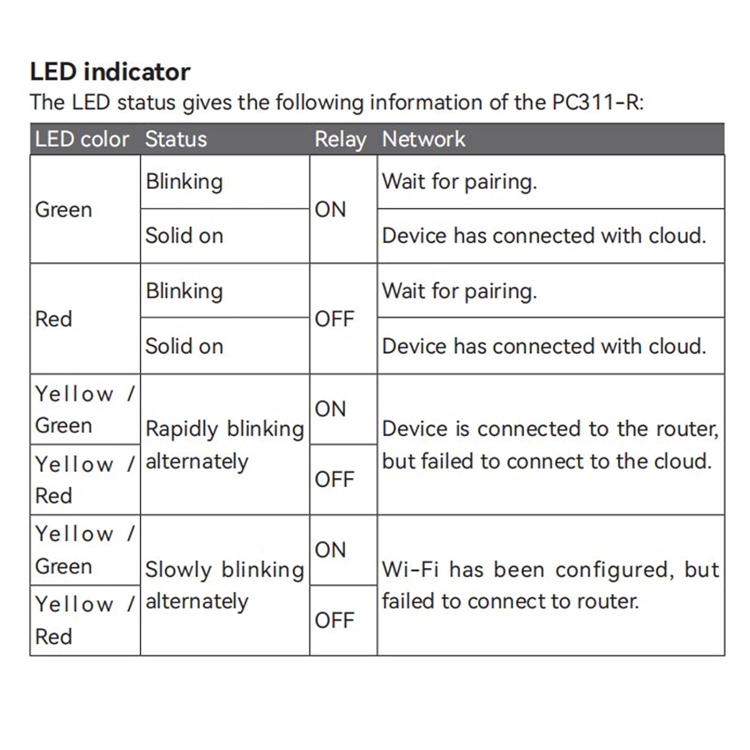
Figure 6: A table detailing the LED indicator status of the Smart Energy Monitor. It explains different LED colors (Green, Red, Yellow/Green, Yellow/Red), their blinking patterns (Blinking, Solid on, Rapidly blinking, Slowly blinking alternately), the corresponding relay state (ON/OFF), and what each status signifies (Wait for pairing, Device connected to cloud, Device connected to router but failed to connect to cloud, Wi-Fi configured but failed to connect to router).
8. การบำรุงรักษา
The Walfront Smart Energy Monitor is designed for minimal maintenance. Follow these guidelines to ensure optimal performance:
- การทำความสะอาด: Periodically wipe the exterior of the device with a soft, dry cloth. Do not use harsh chemicals or abrasive cleaners.
- อัพเดตเฟิร์มแวร์: Ensure the device's firmware is kept up-to-date through the mobile application to benefit from the latest features and security enhancements.
- สภาพแวดล้อม : ตรวจสอบให้แน่ใจว่าสภาพแวดล้อมการทำงานยังคงอยู่ในช่วงอุณหภูมิและความชื้นที่กำหนด
- ตรวจสอบการเชื่อมต่อ: Occasionally inspect wiring connections to ensure they remain secure. Disconnect power before checking connections.
9 การแก้ไขปัญหา
| ปัญหา | สาเหตุที่เป็นไปได้ | สารละลาย |
|---|---|---|
| อุปกรณ์ไม่ได้เปิด | ไม่มีแหล่งจ่ายไฟ, เดินสายไม่ถูกต้อง | Check main power supply and wiring connections (L and N terminals). Ensure circuit breaker is ON. |
| Cannot pair device with app | Incorrect pairing mode; Wi-Fi issues; device too far from router. | Ensure device is in pairing mode (LED blinking). Check Wi-Fi signal strength. Move device closer to router or use a Wi-Fi extender. Verify correct Wi-Fi password. |
| Inaccurate energy readings | ซีที คลamp incorrectly installed or faulty. | Verify CT clamp is installed around the correct live wire and its wires are connected to the CT terminals with correct polarity. Ensure the CT clamp ถูกปิดอย่างเต็มที่ |
| แอปแสดงว่าอุปกรณ์ออฟไลน์ | Wi-Fi disconnected; internet outage. | Check your home Wi-Fi network and internet connection. Restart the monitor by briefly cutting power. Refer to LED status for network issues. |
| 10A dry output not working | Incorrect wiring; app control issue; load exceeding 10A. | Verify wiring to the output terminals. Check app settings and schedules. Ensure the connected load does not exceed 10A. |
10. การรับประกันและการสนับสนุน
For warranty information, technical support, or service inquiries, please refer to the official Walfront webหรือติดต่อฝ่ายบริการลูกค้าโดยตรง โปรดเก็บใบเสร็จรับเงินไว้เป็นหลักฐานการซื้อ
Ask a question about this manual
Ask about setup, troubleshooting, compatibility, parts, safety, or missing instructions. Manuals+ will review the question and use this page’s manual context to help answer it.