
1. สินค้าหมดview
The EPEVER Tracer BN Series MPPT Solar Charge Controller is an advanced, efficient, and multi-functional device designed for off-grid solar systems. It utilizes Maximum Power Point Tracking (MPPT) technology to maximize energy harvest from solar panels, ensuring optimal charging for your battery bank. This controller is suitable for various applications, including telecommunication base stations, household systems, street lighting, and wilderness monitoring systems.
คุณสมบัติที่สำคัญ ได้แก่:
- Advanced MPPT technology with tracking efficiency no less than 99.5% and maximum conversion efficiency of 98%.
- Reliable automatic limit function of maximum PV input power, preventing overload under any circumstances.
- ระบบปฏิบัติการ MPP แบบกว้างtagช่วงอี
- Die-cast aluminum design for excellent heat dissipation.
- ระบบอัตโนมัติ 12/24VDCtagอี บัตรประจำตัว
- Multiple load control modes: manual control, light ON/OFF, light ON+Timer, and time control.
- Supports 4 charging options: Sealed, Gel, Flooded, and User-defined.
- PC monitoring and external display unit (like MT50) connectivity for real-time data checking and parameter setting, with software upgrade support.
- Modbus communication protocol interface for expanded applications and monitoring.
2. ส่วนประกอบผลิตภัณฑ์
Familiarize yourself with the main components and interfaces of the Tracer BN series solar charge controller:

Figure 2.1: Controller Components Overview
This image displays the EPEVER Tracer BN Series Solar Charge Controller with key components labeled, including the Heat Sink, Button, Charging LED indicator, Battery LED indicator, RTS port, RS485 Port, Solar Terminal, Battery Terminal, and Load Terminal.
- ฮีทซิงค์: Dissipates heat generated during operation to maintain optimal performance.
- ปุ่ม: Used for manual control of the load and navigating settings.
- ไฟ LED แสดงสถานะการชาร์จ: Shows the status of PV (solar panel) charging.
- ไฟ LED แสดงสถานะแบตเตอรี่: Displays the battery charging status.
- RTS (Remote Temperature Sensor) Port: Connects an optional remote temperature sensor for accurate battery temperature compensation.
- พอร์ต RS485: Communication interface for connecting to PC, MT50 remote meter, WiFi, or Bluetooth modules.
- Solar Terminal (PV): เชื่อมต่อกับแผงโซลาร์เซลล์
- Battery Terminal (BATT): เชื่อมต่อกับธนาคารแบตเตอรี่
- โหลดเทอร์มินัล: เชื่อมต่อกับโหลด DC
3. การตั้งค่าและการติดตั้ง
Proper installation is crucial for the safe and efficient operation of your solar charge controller. Please follow these steps carefully:
3.1 การแกะกล่องและการตรวจสอบเบื้องต้น
Video 3.1: Unboxing and Component Overview
This video demonstrates the unboxing process of the EPEVER Tracer BN MPPT Solar Charge Controller and provides a visual overview of its main components and ports, including the PV charging LED indicator, battery charging LED indicator, button, PV terminals, battery terminals, load terminals, heat sink, RTS port, and RS485 port.
- Carefully open the packaging and remove the controller and any accessories.
- Inspect the controller for any visible damage. If damage is found, contact your supplier.
- ตรวจสอบให้แน่ใจว่ามีส่วนประกอบทั้งหมดที่ระบุไว้อยู่
3.2 การเชื่อมต่อสายไฟ
หมายเหตุด้านความปลอดภัยที่สำคัญ: While wiring the controller, ensure that the circuit breaker or fuse is ไม่ closed. Verify that the positive ("+") and negative ("-") leads are connected correctly to prevent damage to the controller or other components.
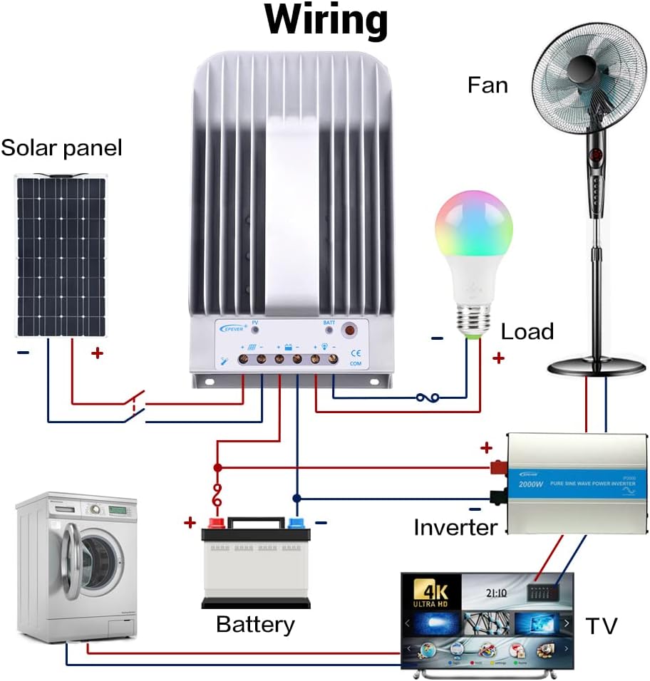
รูปที่ 3.2: แผนภาพการเดินสายระบบทั่วไป
This diagram illustrates a typical solar power system setup, showing the connection of the solar panel to the controller, the controller to the battery, and the controller to various DC and AC loads via an inverter. Ensure correct polarity for all connections.
The connection order is critical:
- เชื่อมต่อแบตเตอรี่: First, connect the battery to the controller's battery terminals. Ensure correct polarity (positive to positive, negative to negative). The controller will automatically detect the system voltage (12V/24V). The controller supports Lead-acid Batteries (Sealed, AGM, Gel, Flooded) and User-defined settings.
- เชื่อมต่อโหลด: Next, connect your DC loads to the controller's load terminals.
- เชื่อมต่อแผงโซลาร์เซลล์ (PV): Finally, connect the solar panel array to the controller's PV terminals.
The disconnection order is the reverse: PV -> Load -> Battery.
Refer to the following table for recommended wire sizes based on controller model:
| แบบอย่าง | Wire Size (AWG/mm²) |
|---|---|
| เทรเซอร์1215BN | 12AWG (4 มม.²) |
| เทรเซอร์2215BN | 8AWG (10 มม.²) |
| เทรเซอร์3215BN | 6AWG (16 มม.²) |
| เทรเซอร์4215BN | 4AWG (25 มม.²) |
4. คู่มือการใช้งาน
Once the controller is correctly wired and powered, it will begin operating automatically. The LED indicators provide visual feedback on the system status.
4.1 การควบคุมโหลด
The controller offers various load control modes. In manual control mode, you can toggle the load on or off using the controller's button.
Video 4.1: Load Manual Mode Operation
This video segment demonstrates how to manually turn the load ON/OFF by pressing the 'ENTER' button on the controller when it is in load manual mode.
Other load control modes (Light ON/OFF, Light ON+Timer, Time Control) can be configured using an external display unit (like MT50) or PC/APP software connected via the RS485 port.
4.2 Monitoring and Parameter Setting
The controller supports various accessories for enhanced monitoring and parameter adjustment:

Figure 4.2: Controller with Communication Accessories
This image illustrates how the solar charge controller can be connected to various communication accessories such as the MT50 remote meter, eBox-WIFI-01 for WiFi monitoring, eBox-BLE-01 for Bluetooth monitoring, and a PC via a USB to RS485 cable for detailed system management.
Optional accessories for monitoring and control:
| อุปกรณ์เสริม | คำอธิบาย |
|---|---|
| Remote Temperature Sensor (RTS300R47K3.81A) | Acquisition of battery temperature for temperature compensation of control parameters. The standard length of the cable is 3m (can be customized). The RTS300R47K3.81A connects to the port (4th) on the controller. บันทึก: If the temperature sensor is short-circuited or damaged, the controller will be charging or discharging at the default temperature 25 °C. |
| USB to RS485 cable (CC-USB-RS485-150U) | USB to RS-485 converter used to monitor each controller on the network using Solar Station PC software. The length of cable is 1.5m. The CC-USB-RS485-150U connects to the RS-485 Port on the controller. |
| OTG cable (OTG-12CM) | Used to connect a mobile communication cable and able to achieve real-time monitoring of the controller and modification of the parameters by using mobile APP software. |
| Remote Meter (MT50) | MT50 can display various operating data and fault of the system. The information can be displayed on a backlit LCD screen, the buttons are easy-to-operate, and the numeric display is readable. |
| WiFi Serial Adapter (eBox-WIFI-01) | After the controller is connected with the eBox-WIFI-01 through the standard Ethernet cable (parallel cable), the operating status and related parameters of the controller can be monitored by the mobile APP software through WiFi signals. |
| RS485 to Bluetooth Adapter (eBox-BLE-01) | After the controller is connected with the eBox-BLE-01 through the standard Ethernet cable (parallel cable), the operating status and related parameters of the controller can be monitored by the mobile APP software through Bluetooth signals. |
| Logger (eLOG01) | หลังจากที่คอนโทรลเลอร์เชื่อมต่อกับ eLOG-01 ผ่านสายสื่อสาร RS485 แล้ว ก็สามารถบันทึกข้อมูลการทำงานของคอนโทรลเลอร์หรือตรวจสอบสถานะการทำงานแบบเรียลไทม์ของคอนโทรลเลอร์ผ่านซอฟต์แวร์พีซี |
บันทึก: For setting and operation of accessories, please refer to their specific instructions.
5. การบำรุงรักษา
การบำรุงรักษาอย่างสม่ำเสมอจะช่วยให้ตัวควบคุมการชาร์จพลังงานแสงอาทิตย์ของคุณมีอายุการใช้งานยาวนานและทำงานได้อย่างมีประสิทธิภาพสูงสุด:
- ความสะอาด : Keep the controller clean and free from dust and debris. Use a dry cloth to wipe the exterior.
- การเชื่อมต่อ: ตรวจสอบความแน่นของจุดเชื่อมต่อสายไฟทั้งหมดเป็นระยะ การเชื่อมต่อที่หลวมอาจทำให้เกิดความร้อนสูงเกินไปและเกิดความเสียหายได้
- การระบายอากาศ : Ensure the heat sink fins are not obstructed to allow for proper airflow and heat dissipation.
- สิ่งแวดล้อม: Operate the controller within its specified ambient temperature and humidity ranges.
6 การแก้ไขปัญหา
If you encounter issues with your EPEVER solar charge controller, consider the following basic troubleshooting steps:
- ไม่มีไฟ/จอแสดงผล: ตรวจสอบการเชื่อมต่อแบตเตอรี่และตรวจสอบปริมาณแบตเตอรี่tage is within the controller's operating range. Verify fuses or circuit breakers are not tripped.
- ไม่มีการชาร์จ: ตรวจสอบให้แน่ใจว่าแผงโซลาร์เซลล์เชื่อมต่ออย่างถูกต้องและได้รับแสงแดดเพียงพอ ตรวจสอบปริมาณอินพุต PVtage and current. Verify PV circuit breaker/fuse.
- โหลดไม่ทำงาน: Check load connections and ensure the load is not exceeding the controller's rated current. Verify the load control mode settings.
- Abnormal LED Indicators: Refer to the full user manual for specific error codes or indicator patterns to diagnose issues.
สำหรับปัญหาที่ซับซ้อนหรือปัญหาที่เกิดขึ้นอย่างต่อเนื่อง โปรดติดต่อฝ่ายสนับสนุนด้านเทคนิค
7. ข้อมูลจำเพาะทางเทคนิค
The following table provides detailed technical specifications for the Tracer BN series, including the 40A model (Tracer4215BN):
Video 7.1: Technical Specifications Overview
This video segment displays a table detailing the technical specifications for the Tracer BN series MPPT Solar Charge Controllers, including electrical and environmental parameters for various models (Tracer1215BN, Tracer2215BN, Tracer3215BN, Tracer4215BN).
| รายการ | Tracer 1215BN | Tracer 2215BN | Tracer 3215BN | Tracer 4215BN |
|---|---|---|---|---|
| ระบบที่กำหนด voltage | อัตโนมัติ 12 / 24VDC | |||
| กระแสไฟชาร์จที่กำหนด | 10เอ | 20เอ | 30เอ | 40เอ |
| กระแสไฟปล่อยที่กำหนด | 10เอ | 20เอ | 20เอ | 20เอ |
| ปริมาณแบตเตอรี่tagช่วงอี | 8V~32V | |||
| แม็กซ์ PV วงจรเปิด voltage | 150V (ที่อุณหภูมิสภาพแวดล้อมการทำงานขั้นต่ำ) 138V (ที่อุณหภูมิแวดล้อม 25°C) | |||
| MPP ฉบับที่tagช่วงอี | ปริมาณแบตเตอรี่tage+2V ~ 108V | |||
| กำลังไฟฟ้าเข้า PV สูงสุด | 130วัตต์(12โวลต์) 260วัตต์(24โวลต์) | 260วัตต์(12โวลต์) 520วัตต์(24โวลต์) | 390วัตต์(12โวลต์) 780วัตต์(24โวลต์) | 520วัตต์(12โวลต์) 1040วัตต์(24โวลต์) |
| การบริโภคเพื่อตนเอง | ≤60mA (12V); ≤30mA (24V) | |||
| วงจรปล่อย voltagอี ดรอป | ≤0.15โวลต์ | |||
| ค่าสัมประสิทธิ์การชดเชยอุณหภูมิ | -3mV/°C/2V (ค่าเริ่มต้น) | |||
| การสื่อสาร | RS485 (อินเทอร์เฟซ RJ45) | |||
| การต่อลงดิน | เชิงลบทั่วไป | |||
| Ambient temperature range* | -35°C ~ +55°C | |||
| ช่วงอุณหภูมิในการจัดเก็บ | -35°C ~ +80°C | |||
| ช่วงความชื้น | ≤95% (NC) | |||
| สิ่งที่แนบมา | IP30 | |||
*Please operate controller at permitted ambient temperature. If over permissible range, please derate capacity accordingly.
8. การรับประกันและการสนับสนุน
EPEVER products are designed for reliability and performance. For warranty information, please refer to the documentation included with your purchase or visit the official EPEVER website. If you require technical assistance or have questions regarding your Tracer BN series solar charge controller, please contact EPEVER customer support or your authorized dealer.