1. บทนำและเรื่องอื่นๆview
The SMARTGEN CMM366A-ET Cloud Monitoring Communication Module is an Ethernet communication protocol switch module designed to connect gensets (with SCI) to the internet. After logging into a cloud server, the module receives the corresponding genset controller communication protocol. It acquires genset data via RS485, USB, LINK, or RS232 ports and transmits this data to the cloud server via wired Ethernet. This enables real-time monitoring of running status and access to historical records through mobile applications (iOS or Android) and PC terminal devices.
Beyond genset monitoring, the CMM366A-ET module also supports digital alarm input/output signals, allowing for monitoring of generator room access, theft prevention, and fire detection facilities.
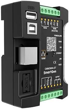
รูปที่ 1 : ด้านหน้า view of the CMM366A-ET module, highlighting the USB, Ethernet, and LINK communication ports.

รูปที่ 2: ด้านหน้าทำมุม view of the CMM366A-ET module, showing the communication ports and the row of LED indicators on the side.
2. สมรรถนะและคุณลักษณะ
- Connects to a cloud server via wired ETHERNET for one-to-one monitoring.
- Features multiple ports for communication with genset control modules: RS485, RS232, LINK, and USB (Host). Capable of monitoring a wide range of international first-class genset control modules.
- Wide power supply range: DC (8~35)V, allowing direct use of the genset's built-in starter battery.
- Equipped with an ARM-based 32-bit SCM for high hardware integration and strong programming capabilities.
- Includes a GPS locate function to acquire location information and track the genset.
- Utilizes JSON network data communication protocol, uploading real-time data variations with a compression algorithm to significantly reduce network traffic.
- Immediately uploads data to the server when an alarm occurs.
- Two auxiliary digital input ports are available for receiving external alarm signals.
- One auxiliary relay output port can output various alarm signals.
- Includes calendar and clock functions.
- Power and multiple communication status indicators on the front panel provide clear operational status at a glance.
- Features a lamp ฟังก์ชั่นการทดสอบ
- Parameters can be adjusted via the USB port.
- Supports standard π-type 35mm guide-rail installation or screw-fixed installation, allowing flexible mounting within the genset control box.
- Modular design with a self-extinguishing ABS plastic shell, offering light weight, compact structure, and easy installation.
3. ข้อมูลจำเพาะ
The following table details the technical specifications of the CMM366A-ET module:
| รายการ | เนื้อหา |
|---|---|
| ปฏิบัติการฉบับที่tage | DC 8.0V~35.0V แหล่งจ่ายไฟต่อเนื่อง |
| การใช้พลังงาน | Standby: ≤2W, Working: ≤5W |
| อินพุตดิจิตอล | อินพุตดิจิตอลแบบไม่มีโวลต์ |
| เอาท์พุตรีเลย์ | เอาต์พุตฟรี 1A DC30V โวลต์ |
| โฮสต์ USB | พอร์ต USB หญิงชนิด A |
| อาร์เอส485 | ชนิดแยก |
| อาร์เอส232 | ประเภททั่วไป |
| ลิงค์ | พอร์ตเฉพาะของ SmartGen |
| อุปกรณ์ USB | พอร์ต USB หญิงชนิด B |
| ETHERNET | อินเทอร์เฟซเครือข่ายการปรับตัวเอง RJ45 10/100Mbps |
| ขนาดเคส | 72.5 มม. x 105 มม. x 34 มม. (ประมาณ 4.13 x 2.87 x 1.38 นิ้ว) |
| เงื่อนไขการทำงาน | Temperature: (-25~+70)°C, Humidity: (20~93)%RH |
| สภาพการเก็บรักษา | อุณหภูมิ: (-25~+70)°C |
| น้ำหนัก | 0.15kg (approx. 6.4 ounces) |
| วัสดุ | Self-extinguishing ABS plastic |
4. การติดตั้งและการตั้งค่า
4.1 การติดตั้ง
The CMM366A-ET module offers flexible installation options. It can be mounted using a standard π-type 35mm guide-rail (DIN rail) or via screw-fixed installation. This allows for convenient placement within a genset control box or other suitable enclosures.
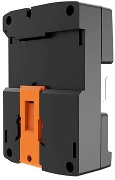
รูปที่ 3: ด้านหลัง view of the CMM366A-ET module, illustrating the integrated orange clip for DIN rail mounting.
4.2 การเดินสายและการเชื่อมต่อ
Proper wiring is essential for the correct operation of the CMM366A-ET module. Refer to the system diagram and terminal descriptions below for guidance.

Figure 4: CMM366A-ET System Diagram. This diagram illustrates how one CMM366A-ET module connects with one genset monitor module via RS485, LINK, RS232, or USB ports. The CMM366A-ET then connects to a router, which communicates with the cloud server, enabling monitoring via cellphone, tablet, or PC.
The CMM366A-ET module connects to a genset controller via one of its communication ports (RS485, LINK, RS232, or USB). It then connects to a network router via its Ethernet port. The router facilitates communication with the cloud server, allowing remote monitoring and control.
Refer to the following table for detailed terminal descriptions and recommended cable sizes:

Figure 5: Terminal Descriptions. This table provides details for each terminal, including its number, function, recommended cable size, and specific notes for connection.
| เลขที่ | การทำงาน | ขนาดสายเคเบิล | บันทึก |
|---|---|---|---|
| 1 | B- | 1.0ตรม. | เชื่อมต่อกับขั้วลบของแบตเตอรี่สตาร์ท |
| 2 | B+ | 1.0ตรม. | ต่อด้วยขั้วบวกของแบตเตอรี่สตาร์ท แนะนำให้ใช้ฟิวส์ 3A |
| 3 | อินพุตดิจิตอล 1 | 1.0ตรม. | ใช้งานเมื่อเชื่อมต่อกับ B- |
| 4 | อินพุตดิจิตอล 2 | 1.0ตรม. | ใช้งานเมื่อเชื่อมต่อกับ B- |
| 5 | Relay Output (Normally Open) | 1.0ตรม. | Normally open output with 1A DC30V. |
| 6 | Relay Output (Common) | 1.0ตรม. | |
| 7 | Relay Output (Normally Close) | 1.0ตรม. | |
| 8 | RS485บี(-) | 0.5ตรม. | แนะนำให้ใช้ลวดป้องกัน Impedance-120Ω โดยมีสายดินด้านเดียว |
| 9 | RS485 เอ(+) | 0.5ตรม. | |
| 10 | ซีอาร์ | 0.5ตรม. | |
| 11 | RS232 RX | 0.5ตรม. | อาร์เอส232 |
| 12 | RS232 เท็กซัส | 0.5ตรม. | |
| 13 | RS232 GND | 0.5ตรม. |
5. คู่มือการใช้งาน
5.1 Panel Indicators and Buttons
The front panel of the CMM366A-ET module features various LED indicators and a button to provide visual feedback on its operational status and for basic control functions.

Figure 6: CMM366A-ET Front Panel Diagram. This diagram labels the various ports and their corresponding LED indicators for power, alarm, and communication status.
Refer to the following table for a description of each indicator:
| ไอคอน | บันทึก |
|---|---|
| พลังงาน/ปลุก | Green LED: Power supply normal indicator Red LED: Common alarm indicator |
| RS485 (สีแดง) | ดับตามปกติ: ปิดใช้งาน RS485 Normally Light: Communication normal กะพริบ: การสื่อสารปกติ |
| USB (สีแดง) | ดับตามปกติ: ปิดใช้งาน USB (โฮสต์) Normally Light: Communication normal กะพริบ: การสื่อสารปกติ |
| ETHERNET (Red) | Normally Extinguish: CMM366A-ET login with server unsuccessfully Normally Light: Login with server successfully กะพริบ: การสื่อสารแบบเรียลไทม์เป็นปกติ |
| LINK (Red) | ดับตามปกติ: ปิดใช้งาน Normally Light: Communication normal กะพริบ: การสื่อสารปกติ |
| RS232 (สีแดง) | ดับตามปกติ: ปิดใช้งาน Normally Light: Communication normal กะพริบ: การสื่อสารปกติ |
| Lamp test/Reset | Press this button for 1s, all the LEDs are illuminated; press for 10s, reset the module to default and all the LEDs blink for 3 times. บันทึก: หลังจากรีเซ็ตโมดูลแล้ว พารามิเตอร์จะต้องได้รับการกำหนดค่าใหม่ผ่านซอฟต์แวร์พีซี โปรดดำเนินการด้วยความระมัดระวัง |
5.2 การทำงานพื้นฐาน
Once the CMM366A-ET module is correctly installed and powered, it will automatically attempt to establish a connection with the configured cloud server via the Ethernet network. The status of this connection and other communication links can be observed through the front panel LED indicators.
- การติดตาม: Real-time data and operational status of the genset can be monitored remotely using the dedicated mobile application (iOS or Android) or through a PC terminal connected to the cloud server.
- การปรับพารามิเตอร์: If necessary, module parameters can be adjusted by connecting a PC to the USB port and using the appropriate PC software.
- การจัดการสัญญาณเตือน: The module will immediately upload alarm data to the server upon detection of an alarm condition from connected digital inputs or the genset controller.
6. การบำรุงรักษา
The CMM366A-ET module is designed for reliable operation with minimal maintenance. To ensure optimal performance and longevity:
- รักษาโมดูลให้สะอาด ปราศจากฝุ่นและเศษขยะ ใช้ผ้านุ่มและแห้งเช็ดทำความสะอาด
- ตรวจสอบให้แน่ใจว่ามีการระบายอากาศที่เพียงพอรอบๆ โมดูลเพื่อป้องกันความร้อนสูงเกินไป
- Periodically inspect all cable connections (power, communication, Ethernet) to ensure they are secure and free from damage.
- Avoid exposing the module to extreme temperatures or humidity outside its specified operating conditions.
- There are no user-serviceable parts inside the module. Do not attempt to open or repair the device yourself.
7 การแก้ไขปัญหา
If you encounter issues with your CMM366A-ET module, refer to the following troubleshooting guide:
- No Power / All Indicators Off:
Check the DC power supply (8~35V) connected to terminals B- and B+. Ensure the power source is active and the wiring is correct. Verify any inline fuses (3A recommended for B+). - Ethernet Communication Issues (ETHERNET LED off or blinking):
Verify the Ethernet cable connection to both the module and the router. Ensure the router is powered on and has an active internet connection. Check network settings and ensure the module is correctly configured to access the cloud server. If the ETHERNET LED is off, it indicates an unsuccessful login to the server. - Genset Communication Issues (RS485, USB, LINK, RS232 LEDs off or blinking):
Check the physical connections between the CMM366A-ET module and the genset controller for the respective communication port. Ensure the genset controller is powered and functioning correctly. If an LED is off, the corresponding port might be disabled or not communicating. - Alarm Indication (Red ALARM LED is lit):
This indicates a common alarm condition. Check the connected auxiliary digital input ports for external alarm signals. Refer to your genset controller's manual for specific alarm codes or conditions. - Module Unresponsive / Unexpected Behavior:
You can perform a reset to factory default parameters. Press and hold the Lamp test/Reset button for 10 seconds. All LEDs will blink three times to confirm the reset. คำเตือน: After a factory reset, all parameters will revert to their default settings and must be re-configured using PC software. Proceed with caution.
8. การรับประกันและการสนับสนุน
Specific warranty information for the SMARTGEN CMM366A-ET module is not provided in this manual. Please refer to the product packaging, purchase documentation, or contact your vendor or SMARTGEN customer service for detailed warranty terms and conditions.
For technical support, assistance with installation, or troubleshooting beyond the scope of this manual, please contact SMARTGEN customer support or your authorized distributor. Ensure you have your product model number (CMM366A-ET) and any relevant purchase details available when seeking support.