
1. บทนำ
This manual provides comprehensive instructions for the safe and efficient operation, installation, and maintenance of the Mean Well RSP-2400-24 AC to DC Power Supply. This high-performance power supply delivers a single 24 Volt output at 100 Amps, providing 2.4 Kilowatts of power. Please read this manual thoroughly before using the product.

รูปที่ 1.1: Mean Well RSP-2400-24 AC to DC Power Supply. This image shows the overall physical appearance of the power supply unit, highlighting its robust metal casing และการเชื่อมต่อเทอร์มินัล
2. คำแนะนำด้านความปลอดภัย
Always observe the following safety precautions to prevent injury or damage to the power supply:
- Ensure proper grounding before connecting the power supply.
- ห้ามใช้งานเครื่องขณะเปียกหรือเปียกamp เงื่อนไข.
- ตรวจสอบปริมาณอินพุตtage and current ratings match your power source.
- หลีกเลี่ยงการปิดกั้นช่องระบายอากาศเพื่อป้องกันความร้อนสูงเกินไป
- บุคลากรที่มีคุณสมบัติเหมาะสมเท่านั้นที่ควรทำการติดตั้งและบำรุงรักษา
- โปรดถอดปลั๊กไฟก่อนทำการเชื่อมต่อหรือปรับแต่งใดๆ
3. คุณสมบัติของผลิตภัณฑ์
The Mean Well RSP-2400-24 power supply incorporates several advanced features:
- AC input active surge current limiting.
- High efficiency up to 90%.
- Built-in active Power Factor Correction (PFC) function (PF>0.95).
- Comprehensive protections: short circuit, overload, over voltage อุณหภูมิเกิน
- Fan alarm and forced air cooling by built-in DC fan with speed control.
- ปริมาณการส่งออกtage trim function (20% to 110% of rated output voltagจ).
- High power density: 12.5W/inch³.
- Current sharing capability for up to 2 units.
- Alarm signal output via relay contact and TTL signal.
- Output connector type: Lug terminal female.
4. ข้อกำหนดทางกล
Detailed mechanical dimensions and component layout are provided below for installation planning.
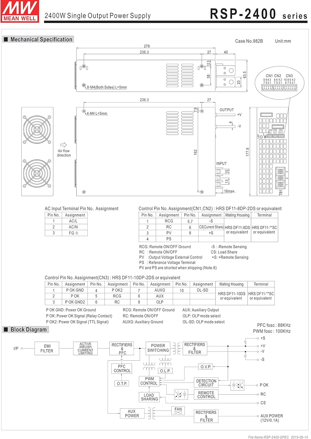
รูปที่ 4.1: Mechanical drawing of the RSP-2400 series power supply. This diagram illustrates the physical dimensions, mounting hole locations, and general layout of the input/output terminals and cooling fans. Key dimensions are provided in millimeters.
The diagram shows the overall dimensions of 278mm (L) x 177.8mm (W) x 63.5mm (H), along with details for mounting holes (M4, L=5mm) and air flow direction for the cooling fans.
5. การตั้งค่าและการติดตั้ง
5.1. AC Input Terminal Pin Assignment
Connect the AC input according to the following pin assignments:
รูปที่ 5.1: AC Input Terminal Pin Assignment. This section of the mechanical drawing details the connections for the AC input, including AC/L, AC/N, and FG (Frame Ground) terminals.
| หมายเลขพิน | งานที่มอบหมาย |
|---|---|
| 1 | ไฟฟ้ากระแสสลับ/ลิตร |
| 2 | แอร์/ไม่มี |
| 3 | FG |
5.2. Control Pin No. Assignment
The control pins (CN1, CN2, CN3) allow for remote control and monitoring functions. Refer to the diagram for detailed assignments.
รูปที่ 5.2: Control Pin No. Assignment for CN1, CN2, and CN3. This part of the mechanical drawing provides a detailed pinout for the control connectors, including functions like Remote ON/OFF, Current Share, and Auxiliary output.
| หมายเลขพิน | งานที่มอบหมาย | ที่อยู่อาศัยผสมพันธุ์ | เทอร์มินัล |
|---|---|---|---|
| 1 | อาร์ซีจี | HRS DF11-8DP-2DS หรือเทียบเท่า | HRS DF11-**SC หรือเทียบเท่า |
| 2 | RC | ||
| 3 | PV | ||
| 4 | PS | HRS DF11-8DS หรือเทียบเท่า | HRS DF11-**SC หรือเทียบเท่า |
| 5 | CS (Current Share) | ||
| 6 | +S | ||
| 7 | -S |
RCG: Remote ON/OFF Ground
อาร์ซี: เปิด / ปิดรีโมต
พีวี: ปริมาณการส่งออกtage การควบคุมภายนอก
ป.ล.: Power Supply Status Signal
ซีเอส: โหลดแชร์
+S, -S: Remote Sensing (Note 6)
| หมายเลขพิน | งานที่มอบหมาย | หมายเลขพิน | งานที่มอบหมาย | หมายเลขพิน | งานที่มอบหมาย | ที่อยู่อาศัยผสมพันธุ์ | เทอร์มินัล |
|---|---|---|---|---|---|---|---|
| 1 | พี โอเค GND | 6 | อาร์ซีจี | 10 | OL-SD | HRS DF11-10DP-2DS หรือเทียบเท่า | HRS DF11-**SC หรือเทียบเท่า |
| 2 | พี่โอเค | 7 | RC | ||||
| 3 | พี โอเค GND2 | 8 | อ๊อกซ์ | ||||
| 4 | พี โอเค2 | 9 | AUXG | ||||
| 5 | พี โอเค GND |
P OK: สัญญาณเพาเวอร์ตกลง (หน้าสัมผัสรีเลย์)
P OK2: สัญญาณไฟตกลง (สัญญาณ TTL)
ช่องเสริม: เอาต์พุตเสริม
AUXG: พื้นเสริม
OL-SD: OLP mode select
อปท.: OLP mode select
5.3. Three Phase Connection
The RSP-2400 series can be configured for 3-phase power systems. Refer to the diagrams for standard configurations.

รูปที่ 5.3: Three Phase Connection Diagrams. This image displays three different configurations for connecting the RSP-2400 units to a 3-phase power system: 3-wire 220VAC, 3-wire 220/380VAC, and 3-wire 190/110VAC systems. Each diagram shows the wiring for multiple units (Unit 1, Unit 2, Unit 3) and their connection to the R, N, T, and FG lines.
- FIG. A: 3∅ 3W 220VAC SYSTEM (STANDARD MODEL FOR STOCK): Illustrates connection for a 3-wire, 220VAC three-phase system.
- FIG. B: 3∅ 4W 220/380VAC SYSTEM: Illustrates connection for a 4-wire, 220/380VAC three-phase system.
- FIG. C: 3∅ 4W 190/110VAC SYSTEM: Illustrates connection for a 4-wire, 190/110VAC three-phase system.
6. การดำเนินการ
6.1. Remote ON/OFF Function
The power supply can be remotely turned ON or OFF by applying voltage to the control pins (CN1 & CN2 & CN3). Refer to the following table and diagrams for connection exampเลส.
| วิธีการเชื่อมต่อ | ภาพที่ 1.2(A) | มะเดื่อ 1.2(B) | มะเดื่อ 1.2(C) |
|---|---|---|---|
| SW ลอจิก | เปิดเอาต์พุต | สว.เปิด | สว.เปิด |
| เอาต์พุตปิด | SW ปิด | SW ปิด |

รูปที่ 6.1: Examples of connecting remote ON/OFF. This image provides three circuit diagrams (A, B, C) illustrating different methods for implementing the remote ON/OFF function using external voltage sources or the internal 12V auxiliary output, showing connections to AUX, RCG, RC, SW, and AUXG pins.
- (A) Using external voltagที่มา: Connect an external 12V source to control the SW pin.
- (B) Using internal 12V auxiliary output: Utilize the power supply's internal 12V AUX output for control.
- (C) Using internal 12V auxiliary output: Another configuration using the internal 12V AUX output for control.
6.2. เอาต์พุตสัญญาณเตือนภัย
The power supply provides alarm signals via P OK and P OK2 GND pins. An external voltagจำเป็นต้องใช้ e source สำหรับฟังก์ชันนี้
| การทำงาน | คำอธิบาย | Output of alarm (P OK, Relay Contact) | Output of alarm (P OK2, TTL Signal) |
|---|---|---|---|
| พี่โอเค | The signal is "Low" when the power supply is above 80% of the rated output voltage. | ต่ำ (สูงสุด 0.5V ที่ 500mA) | ต่ำ (สูงสุด 0.5V ที่ 10mA) |
| The signal turns to be "High" when the power supply is under 80% of the rated output voltage or Power Fail. | สูงหรือเปิด (ใช้ภายนอก voltagจ, สูงสุด 500mA) | สูงหรือเปิด (ใช้ภายนอก voltagจ, สูงสุด 10mA) |

รูปที่ 6.2: Internal circuit of P OK (Relay, total is 10W) and P OK2 (Open collector method). These diagrams show the internal circuitry for the alarm signal outputs, including connections for external voltage and resistance for both P OK and P OK2.
6.3. ปริมาณการส่งออกtagอี ทริม
ปริมาณการส่งออกtage can be trimmed between 20% and 110% of the rated output voltage. The PV (PIN3) and PS (PIN4) of CN1 or CN2 must be disconnected if "Output Voltage TRIM" function is used. Otherwise, the internal electrical components may be damaged, and the power supply unit may thus be out of order.
รูปที่ 6.3: ปริมาณการส่งออกtage Trimming. This section of the image includes a diagram showing how to add an external 1-6V external voltage for trimming, and two graphs: one illustrating output voltage vs. external voltage, and another showing output current vs. output voltage เปอร์เซ็นต์tage.
- Connect +S and -S to the load.
- Connect +V and -V to the load.
- การปรับปริมาณการส่งออกtage is possible between 20-110% (Typ.) of the rated output which is shown in Fig. 3.2. Reducing output current is required when the output voltage is trimmed up.
6.4. การแบ่งปันปัจจุบัน
Up to 2 units can share current in parallel. For optimal performance, ensure the voltage difference among each output should be minimized (less than 0.2V).

รูปที่ 6.4: Current Sharing Connection. This diagram illustrates how to connect multiple RSP-2400 units (Master, Slave 2, Slave 3) in parallel for current sharing, showing the connections for AC/L, AC/N, FG, +V, -V, +S, and -S terminals.
- Connect +S, -S, and CS (Current Share) pins in parallel.
- The total output current must not exceed the value determined by the following equation: (Output current at parallel operation) = (Rated output per unit) × (Number of unit) × 0.9.
- For parallel operation with 3 units or more, consult the manufacturer for specific applications.
- Ensure remote sensing wires are kept at least 10 cm from input wires.
- Under parallel operation, the "output voltage trim" function is not available.
- When in parallel operation, the minimum output load should be greater than 3% of total output load (Min. Load >3% rated current per unit × number of unit).
6.5. OLP Select (Overload Protection)
The OLP (Overload Protection) mode can be selected by modifying the connector on CN3.
รูปที่ 6.5: OLP Mode Selection. This section of the image shows two diagrams: one for removing the shorting connector on CN3 for "constant current limiting" OLP mode, and another for inserting the shorting connector on CN3 for "constant current limiting with delay shutdown after 5 seconds" OLP mode.
- Removing the shorting connector on CN3: The O.L.P. mode will be "continuous constant current limiting".
- Inserting the shorting connector on CN3: The O.L.P. mode will be "constant current limiting with delay shutdown after 5 seconds, re-power on to recover".
7. การบำรุงรักษา
Regular maintenance ensures the longevity and reliable operation of your power supply.
- การทำความสะอาด: Periodically clean the exterior of the unit and ventilation openings with a soft, dry cloth. Ensure the power supply is disconnected from all power sources before cleaning. Do not use liquid cleaners.
- การตรวจสอบ: Regularly inspect cables and connections for any signs of wear, damage, or loose connections.
- การระบายอากาศ : Ensure that the area around the power supply is clear and that airflow to the cooling fans is not obstructed.
- สภาพแวดล้อม : Operate the power supply within its specified temperature and humidity ranges.
8 การแก้ไขปัญหา
หัวข้อนี้ให้แนวทางแก้ไขปัญหาทั่วไปที่คุณอาจพบเจอ
| ปัญหา | สาเหตุที่เป็นไปได้ | สารละลาย |
|---|---|---|
| ไม่มีเอาต์พุต voltage | No AC input power; Remote ON/OFF is OFF; Internal fuse blown; Overload protection activated. | Check AC input connection and power source; Verify Remote ON/OFF settings; Contact service if fuse is suspected; Reduce load and cycle power. |
| ปริมาณการส่งออกtagไม่เสถียร | Loose connections; Overload; Faulty load. | Check all connections; Ensure load is within specifications; Test with a different load. |
| ความร้อนสูงเกินไป | Blocked ventilation; Excessive ambient temperature; Overload. | Clear obstructions from vents; Ensure adequate airflow; Reduce ambient temperature; Reduce load. |
| พัดลมไม่ทำงาน | Fan failure; Unit not under sufficient load/temperature to activate fan. | Check if the unit is hot enough to require fan operation; If fan still doesn't work when hot, contact service. |
หากปัญหายังคงมีอยู่หลังจากพยายามแก้ไขปัญหาเหล่านี้แล้ว โปรดติดต่อฝ่ายสนับสนุนลูกค้า
9. ข้อมูลจำเพาะ
Key technical specifications for the Mean Well RSP-2400-24 AC to DC Power Supply:
| พารามิเตอร์ | ค่า |
|---|---|
| หมายเลขรุ่น | RSP--ฮิตฮิต |
| ยี่ห้อ | มีนเวลล์ |
| ปริมาณการส่งออกtage | 24 โวลต์ |
| กระแสไฟขาออก | 100 Amps |
| เอาท์พุต วัดtage | 2400 วัตต์ |
| ประสิทธิภาพ | สูงสุดถึง 90% |
| การแก้ไขตัวประกอบกำลัง (PFC) | Active PFC, PF>0.95 |
| ขนาด (กว้าง x ยาว x สูง) | 11.02 x 7.09 x 2.56 นิ้ว (278 x 177.8 x 63.5 มม.) |
| น้ำหนัก | 7.28 ปอนด์ (3.3 กิโลกรัม) |
| วิธีการทำความเย็น | ระบบระบายความร้อนด้วยอากาศบังคับโดยพัดลม DC ในตัว |
| การคุ้มครอง | ไฟฟ้าลัดวงจร, โอเวอร์โหลด, ปริมาตรเกินtagจ อุณหภูมิเกิน |
| ประเภทขั้วต่อ | Lug terminal female |
| อุปกรณ์ที่รองรับ | คอมพิวเตอร์ส่วนบุคคล (Note: This is a general classification, actual compatibility depends on power requirements.) |
10. การรับประกันและการสนับสนุน
For warranty information and technical support, please refer to the official MEAN WELL webเยี่ยมชมเว็บไซต์หรือติดต่อตัวแทนจำหน่ายที่ได้รับอนุญาตของคุณ เก็บใบเสร็จรับเงินไว้เป็นหลักฐานการซื้อเพื่อใช้ในการเรียกร้องการรับประกัน
หากต้องการความช่วยเหลือเพิ่มเติม โปรดไปที่: www.meanwell.com